In many audio systems, the point where sound enters the equipment determines how well everything that follows will perform. A signal that arrives with the wrong level, unstable grounding, poor shielding, or improper impedance conditions may still pass through the system, but the final result often includes noise, distortion, weak output, or processing errors that become difficult to correct later. This is why line input remains an important engineering topic even in systems that are increasingly digital.
Audio input in the form of line input is used to receive analog audio signals that are already stronger than microphone-level signals and are intended to be transferred into mixers, amplifiers, recorders, DSP units, codecs, intercom systems, public address platforms, and other electronic processing equipment. Its role is not simply to accept sound from another device. It must preserve signal integrity, support stable transmission, protect downstream circuits, and create a predictable interface between external audio sources and the internal architecture of a system.
Understanding line input requires looking beyond a connector or a labeled port. It involves signal level standards, electrical interface behavior, impedance relationships, balanced and unbalanced transmission methods, analog conditioning stages, anti-interference design, and the practical requirements of real deployment environments. In communication systems, industrial sites, transport hubs, paging networks, and professional media systems, line input is often the boundary where signal quality is either protected or compromised.
Where line-level signals sit in the audio chain
Audio systems usually contain several signal domains, and each domain has a different electrical behavior and engineering purpose. At one end is the acoustic world, where microphones convert sound pressure into very small electrical signals. At the other end are loudspeakers or headphones that convert processed electrical signals back into sound. Between these two ends lies a signal chain made up of preamplification, routing, processing, control, and output stages. Line-level audio occupies an important middle layer in this chain.
A line-level signal is stronger than a microphone signal and normally does not require the large gain increase associated with microphone preamplifiers. That makes line input especially suitable for accepting signals from devices such as media players, mixers, wireless receiver outputs, broadcast consoles, paging controllers, communication gateways, playback modules, and external audio interfaces. In practical terms, it is the standard method for carrying audio from one piece of equipment to another within a system.
This intermediate position is why line input has system-wide importance. If a microphone signal is too weak, preamplification can help. If a power amplifier output is too strong, attenuation or matching devices may be required. But a line input stage is expected to accept a signal that is already in a usable range and carry it forward without fundamentally altering its content. Its task is controlled transfer rather than major amplification.
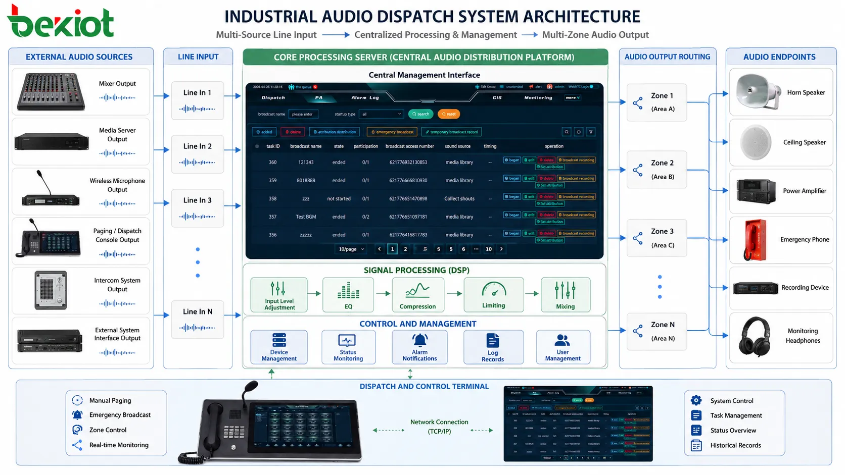
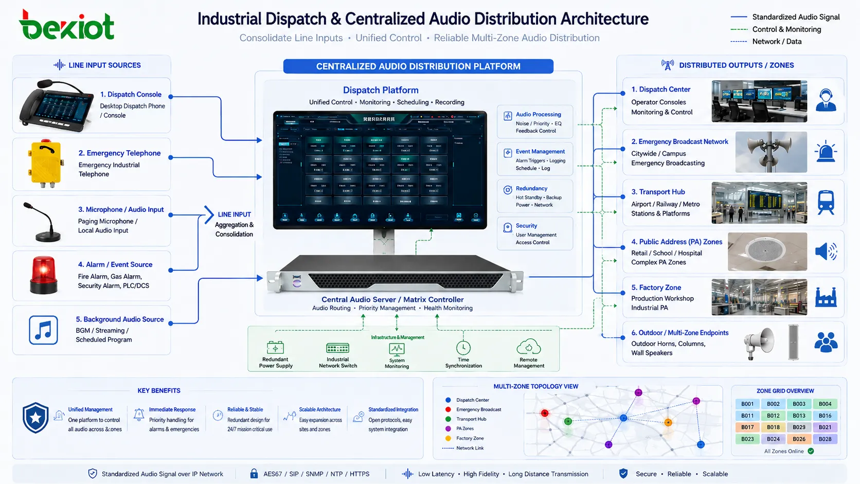
In integrated platforms such as public address systems, voice alarm systems, dispatch consoles, industrial communication servers, or recording systems, line input often acts as the universal bridge between subsystems. A paging source, a control room playback source, a radio receiver output, and an external announcement interface may all enter the platform through line-level channels. That makes line input an interoperability layer as much as an electrical interface.
What makes line input different from microphone input
One of the most common misunderstandings in audio integration is assuming that any audio connector can accept any audio source as long as the plug fits. In reality, microphone input and line input are designed for very different signal conditions. A microphone produces a very small voltage, often requiring substantial preamplification before it becomes suitable for processing. A line source, by contrast, usually provides a much higher voltage and is already at a level intended for inter-equipment transfer.
If a line-level source is connected to a microphone input, the receiving stage may overload because the input is expecting a much weaker signal. This often results in distortion, clipping, or limited usable adjustment range. If a microphone is connected directly to a line input, the opposite problem appears: the signal may be too weak, too noisy, or too low for effective system use because the receiving stage is not providing enough gain.
The difference is not only about level. Microphone inputs often include features such as phantom power, very high gain range, low-noise preamplification, and sensitivity to cable and shielding quality. Line inputs generally focus more on level compatibility, stable impedance behavior, and efficient transport into the next stage of the system. They are engineered for acceptance of already-conditioned signals rather than raw transducer output.
In communication and industrial systems, this difference matters during integration work. For example, when an alarm controller needs to inject a pre-recorded alert tone into a paging amplifier, or when a dispatch system sends monitoring audio into a recorder, the interface is usually line-level. The system is not looking for a microphone source; it is looking for a stable electronic audio feed that can be routed, monitored, or converted without high-gain preamplification.
Choosing the correct input type therefore affects more than loudness. It affects noise floor, dynamic range, distortion margin, operational stability, and compatibility with the rest of the installation. In larger systems, incorrect use of microphone and line interfaces can create confusing service issues that appear to be software or DSP problems but are actually caused by basic front-end signal mismatch.
The electrical principle behind receiving a line-level signal
At the electrical level, line input works by accepting an alternating analog voltage waveform from a source device and transferring that waveform into the receiving circuit under controlled conditions. The receiving stage is designed to recognize the expected voltage range, maintain a suitable input impedance, reject unwanted DC components where necessary, and preserve the frequency content of the signal before passing it onward to amplifiers, converters, or digital processors.
Line-level references vary by market and equipment class. Consumer devices commonly use levels around -10 dBV, while professional systems typically use +4 dBu as a nominal standard. Although real signals fluctuate above and below these reference points, the existence of nominal standards allows designers to build interoperable systems. A well-designed line input stage can accept the expected operating range while providing enough headroom to handle peaks without clipping.
The receiving circuit usually presents a relatively high input impedance compared with the source output impedance. This is intentional. The goal is not maximum power transfer, as in some other electrical systems, but stable voltage transfer with minimal loading of the source. By avoiding excessive current draw from the source device, the line input helps preserve signal amplitude and minimize distortion.
Capacitors may be used for AC coupling so that unwanted DC offset from the source does not disturb the internal operating point of the receiving equipment. Resistor networks establish biasing or reference conditions. Protection components may guard against transient overvoltage events. In some designs, transformer isolation or differential receiver stages are used to improve common-mode noise rejection and ground isolation.
From a principle standpoint, line input is therefore a controlled acceptance stage. It does not simply “listen” to audio. It creates a stable electrical environment in which an incoming analog waveform can enter the system with minimal alteration, sufficient protection, and predictable compatibility with the downstream signal path.
Input stage design: from connector to usable internal signal
Behind a line input connector there is usually more engineering than the front panel suggests. The visible port may be a 3.5 mm jack, RCA pair, terminal block, XLR connector, or 6.35 mm jack, but after the connector the signal normally passes through several internal stages before it becomes usable inside the equipment. These stages define much of the system’s real-world performance.
The first part of the path is usually the physical interface and protection layer. This section may include connector grounding strategy, electrostatic discharge protection, and transient suppression. In environments where cables are frequently connected and disconnected, or where field wiring is long and exposed to electrical disturbance, this layer helps prevent damage and operational instability.
Next comes conditioning and interface control. AC coupling may remove DC offset, while filtering may suppress radio-frequency interference or very low-frequency disturbances that are not part of the intended audio band. Some systems include selectable sensitivity or gain trim here so that sources from different equipment classes can be normalized into a usable operating range. Others provide switchable balanced or unbalanced acceptance depending on installation needs.
After this, the signal may pass through a buffer stage or line receiver that stabilizes impedance behavior and isolates the source from downstream circuitry. In digitally controlled platforms, the signal then moves toward an analog-to-digital converter so that DSP, routing logic, equalization, gain control, mixing, recording, or network transmission functions can act on it. In more analog-oriented systems, it may instead go into tone control, matrix switching, or direct amplifier stages.
The quality of this input path influences both objective performance and operational usability. A poorly designed stage may allow hum, clip easily, handle only a narrow input range, or become unstable when connected to long field wiring. A well-designed stage accepts typical line sources gracefully, rejects predictable interference, and presents the rest of the system with a clean and stable signal foundation.
Balanced and unbalanced paths in real installations
One of the most important practical topics in line input engineering is the difference between balanced and unbalanced transmission. Both methods carry audio, but they behave differently in the presence of electrical noise, long cable runs, and complex grounding conditions. Understanding this distinction is essential when designing or troubleshooting installations beyond a simple desktop setup.
An unbalanced connection typically uses one conductor for the signal and one conductor as the reference or shield. This method is common in consumer equipment and short cable runs because it is simple and cost-effective. However, it is more vulnerable to external noise pickup and grounding problems, especially when cables are long or when devices are powered from different sources in electrically noisy environments.
A balanced connection uses two signal conductors carrying equal and opposite versions of the audio waveform, plus a shield. The receiving stage measures the difference between the two conductors. Noise that is induced equally onto both conductors tends to be rejected as common-mode interference. This makes balanced interfaces especially valuable in professional audio systems, industrial control rooms, transportation sites, and communication infrastructure rooms where long cable runs and electrical disturbance are common.
The choice between balanced and unbalanced is not just theoretical. In a factory paging system, a control room source may need to feed an amplifier rack located far away from the source equipment. In a dispatch environment, console monitoring audio may be carried across racks and patch systems close to power supplies, network switches, or radio equipment. In such conditions, a balanced line input provides much better resistance to hum and interference.
That said, balanced wiring is not a magical solution to every problem. Shield bonding, grounding strategy, cable quality, connector termination, and the actual design of the receiver stage all affect the final result. A poorly implemented balanced system can still perform badly. But when engineered correctly, balanced line input is one of the most reliable ways to move analog audio through demanding environments.
Impedance, loading, and why interface matching matters
Impedance is often discussed in simplified terms, but in line input work it has very practical consequences. The output stage of a source device and the input stage of a receiving device form an electrical relationship. If the receiving input places an unsuitable load on the source, the signal can be weakened, distorted, or frequency-shaped in undesirable ways. Good line input design avoids this by presenting a high enough input impedance to support stable voltage transfer.
In most audio line systems, the source impedance is relatively low and the input impedance is relatively high. This is sometimes described as impedance bridging rather than exact matching. The intention is not to maximize delivered power but to ensure that the source does not have to work too hard to drive the destination. This approach helps preserve the waveform while keeping level loss small.
Cable capacitance, connector quality, and source drive capability all affect the real behavior of the connection. In short cable runs with well-designed devices, the influence may be modest. In long runs or when devices are marginally designed, the combination can soften high-frequency response, change transient clarity, or make the interface more sensitive to noise. What appears to users as “dull audio” or “weak signal” can sometimes be traced back to front-end loading conditions rather than a downstream processing problem.
Input impedance also influences compatibility when one source must feed multiple destinations. Passive splitting can change the effective load seen by the source, increasing the risk of level reduction or tonal changes. In such situations, active distribution amplifiers or proper buffering are usually better engineering choices than simple parallel wiring.
This is why interface planning matters. A line input is not just a socket with a nominal level label. It is an electrical behavior model. In professional and industrial systems, the best results come from treating source characteristics, destination impedance, wiring length, and distribution method as part of one integrated design problem.
Noise control, grounding, and interference management
Many line input problems that appear to be “audio quality issues” are actually interference and grounding issues. Because line input accepts an analog waveform, it remains vulnerable to electrical contamination before digitization or amplification. Once noise enters at the front end, later processing may reduce it only partially, and sometimes not at all. Preventing contamination at the input stage is therefore more effective than trying to repair it later.
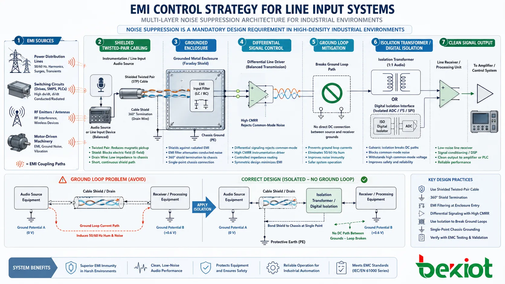
Ground loops are among the most common causes of unwanted hum and buzz. They occur when two pieces of connected equipment sit at different ground potentials and the audio cable becomes part of an unintended current path. The result can be a persistent low-frequency noise, often related to mains power frequency and its harmonics. In larger sites with multiple power zones, this problem becomes more common rather than less.
Electromagnetic interference is another major factor. Motors, switching power supplies, radio transmitters, lighting systems, network equipment, and industrial control circuits can all induce unwanted energy into nearby audio paths. If an unbalanced cable is routed poorly or shielding is weak, the line input stage may receive both the intended audio and a layer of contamination riding on top of it.
Good engineering practice combines several methods to reduce risk. Balanced transmission is preferred for longer or noisier environments. Cable routing should separate audio from strong power and RF sources. Shield termination must be chosen with awareness of system grounding strategy. Isolation transformers, differential receivers, and input filtering can provide additional protection where conditions are difficult. Equipment racks and field enclosures should also be designed with attention to cable entry, earthing, and segregation.
In practical maintenance work, noise control often requires both measurement and observation. Listening tests help identify the character of the problem, while meters and analyzers reveal whether the issue is broadband noise, a grounding-related hum, RF ingress, overload artifacts, or switching interference. Effective line input design reduces the probability of such issues, but effective deployment practice is what keeps them under control in the field.
How line input supports conversion, DSP, and networked audio
In many current systems, the line input stage is not the final destination of the analog signal. It is the gateway into a broader internal workflow that may include analog-to-digital conversion, DSP-based gain control, equalization, echo handling, mixing, recording, codec processing, network transport, or event-driven playback logic. The quality of the signal entering through the line input has a direct effect on all of these downstream processes.
Once the signal reaches the converter stage, it is sampled and quantized into digital form. At that point, the system can manipulate it with great flexibility, but it cannot restore information that was already lost or damaged at the input. Distortion caused by overload, hum introduced by grounding faults, or poor frequency balance caused by interface issues may become part of the digital stream and remain present throughout the rest of the chain.
In communication platforms, line input is often used to inject audio from external systems into digital switching or transmission infrastructure. A tone source may feed a paging controller. A monitoring receiver may feed a recorder. A control center may inject local announcements into an IP-based public address network. A dispatch platform may take analog program audio and forward it through digital routing and processing layers. In each of these cases, the line input determines whether the external source becomes a clean internal resource or a recurring service problem.
DSP features such as automatic gain control, equalization, compression, ducking, or source priority can improve system behavior, but they assume a basically healthy input signal. If the input is severely overdriven or contaminated, DSP may make the symptoms more complex rather than solving the root cause. This is why front-end engineering remains important even in highly digital platforms.
The more a system depends on integration, automation, and centralized audio control, the more valuable a stable and well-designed line input becomes. It is the first control point in the chain, and its quality shapes what the rest of the system can achieve.
Typical application scenarios across communication and control systems
Line input appears in a wide range of practical applications because it supports clean transfer of audio between devices. In public address and voice alarm systems, it is commonly used for background music sources, emergency tone generators, operator consoles, external paging interfaces, and media playback devices. In these environments, line input allows multiple content sources to be introduced into a single platform and routed according to priority logic.
In industrial communication systems, line inputs may receive audio from production control rooms, monitoring stations, radio gateways, or locally generated alerts. The signals can then be distributed through amplifiers, intercom servers, loudspeaker systems, or recording platforms. Because industrial environments often involve long cabling distances and electrical noise, the line input stage needs to support robust interface behavior rather than merely acceptable laboratory performance.
Dispatch and command environments also rely on line-level interfaces. Monitoring audio, recording feeds, external playback sources, and auxiliary system integration often occur at line level. For example, a control center might send a recorded guidance message into a dispatch audio matrix, or an external system might feed a tone or alert into a console supervision chain. The line input provides the structured way to bring those signals into the operational workflow.
Broadcast and production environments use line input as a routine interconnection method between mixers, processors, playback systems, and recorders. Although the quality expectations here are high, the underlying engineering principles remain the same: correct level, suitable impedance, noise control, and stable handling of the source.
These varied use cases show why line input analysis should not be limited to one device type. It is a common building block across many system classes, and the lessons of good implementation apply broadly wherever analog audio must enter an electronic platform.
Deployment considerations, maintenance, and troubleshooting
Good line input performance depends as much on deployment practice as on circuit design. Field problems often originate in connectors, wiring, routing paths, gain settings, or interface assumptions rather than in the internal electronics of the equipment itself. A technically capable device can still deliver poor results if the installation does not respect basic audio engineering practice.
One of the first deployment considerations is source identification. Engineers should confirm whether a device is truly providing line-level output, whether that output is balanced or unbalanced, what nominal level standard it follows, and whether its grounding behavior creates any special considerations. This prevents incorrect assumptions that later cause overload, low level, or noise problems.
Cable selection and routing are equally important. Long analog paths should use appropriate shielding and, where possible, balanced transmission. Audio cables should be kept away from high-power circuits, switching devices, and strong RF sources. Connector termination should be secure and consistent. In control rooms and equipment racks, documentation of source and destination paths is worth the effort because troubleshooting becomes much faster when the signal chain is clearly known.
When faults do occur, a structured troubleshooting method works best. Start by verifying whether the source signal is present and healthy. Then confirm that the correct input type and sensitivity are being used. Inspect cabling and grounding. If noise is present, determine whether it resembles hum, hiss, crackle, RF contamination, or overload distortion. If the level is low, check both source output settings and possible passive loading. If the audio is distorted, investigate clipping at the source or at the receiving stage before assuming DSP or amplifier failure.
Routine maintenance also matters in long-life systems. Connectors oxidize, cable strain increases, grounding changes after equipment moves, and expansion work sometimes introduces new interference paths. A line input channel that worked perfectly at commissioning can degrade gradually over time. Periodic inspection and listening checks help preserve system reliability before users experience service-impacting failure.
Choosing the right line input approach for a project
Selecting the right line input arrangement is not simply a matter of picking a connector style. It involves understanding the role of the source, the environment, the transmission distance, the expected level range, and the functions of the receiving system. A compact local playback source feeding a nearby amplifier has very different requirements from a control room source feeding a distributed paging network across an industrial site.
For short, low-noise connections in small systems, an unbalanced line input may be perfectly adequate. For larger systems, balanced inputs are generally the safer choice, especially when the project includes long runs, mixed power environments, or multiple equipment rooms. If the system must integrate many external sources, input level adjustment, monitoring capability, and robust overload tolerance become more important. If the site is electrically harsh, isolation and filtering deserve stronger emphasis.
Where the audio will enter a digital platform, the quality of the line input should be considered alongside converter quality and DSP architecture. There is little value in advanced processing if the front end is unstable. Likewise, if the system must support expansion, the chosen interface strategy should make future integration easier rather than harder. Standardized wiring, documentation, and predictable signal levels contribute greatly to long-term maintainability.
Ultimately, the right line input approach is the one that matches the source behavior, protects signal integrity, supports the operating environment, and fits the broader system architecture. Good choices at this stage reduce commissioning time, simplify maintenance, and improve user confidence in the entire audio platform.
FAQ
Can a line input accept output from any external audio device?
Not automatically. The device may provide a signal that is too high, too low, balanced instead of unbalanced, or electrically unsuitable for the receiving stage. The connector alone does not guarantee compatibility. The nominal output level, interface type, grounding behavior, and whether the source is fixed or adjustable should all be checked before connection.
Why does a line input sometimes sound clean at low volume but distort when the source is increased?
This usually indicates overload at some point before or within the receiving input stage. The source may be delivering a hotter signal than the input expects, or the input trim may be set too aggressively. Even if the downstream amplifier or DSP has spare capacity, distortion can already be occurring at the front end where the analog waveform first enters the system.
When is transformer isolation useful on a line input channel?
Transformer isolation is often useful when equipment is located on different power systems, when ground loop problems are recurring, or when long field wiring creates unpredictable electrical relationships. It can help break unwanted ground paths and improve immunity to hum, though it must be selected carefully so that bandwidth and signal quality remain appropriate for the application.
Is a digital audio system less dependent on good line input design?
No. A digital system still depends heavily on the quality of the analog signal entering it. Once noise, hum, or clipping is introduced before conversion, the converter captures those problems and the DSP works with a compromised signal. Digital processing adds flexibility, but it does not remove the need for solid front-end interface design.
What should be checked first when a line input channel suddenly becomes noisy?
Start with the simplest and most failure-prone items: the source device, cable integrity, connector seating, and any recent changes in power or grounding conditions. Then determine whether the noise is constant or appears only when certain nearby equipment operates. This helps distinguish between source-related issues, cabling faults, grounding problems, and environmental interference.